Liquid chrome: designing a mower, and drawings that can't lie
The brief was "a really slick mower", plus electrical diagrams, a circuit-board plan, software architecture, mechanical drawings and renders. Here's how a software project designs hardware: everything is generated from code, and the drawings check themselves.
The shape, and the engineering it had to obey
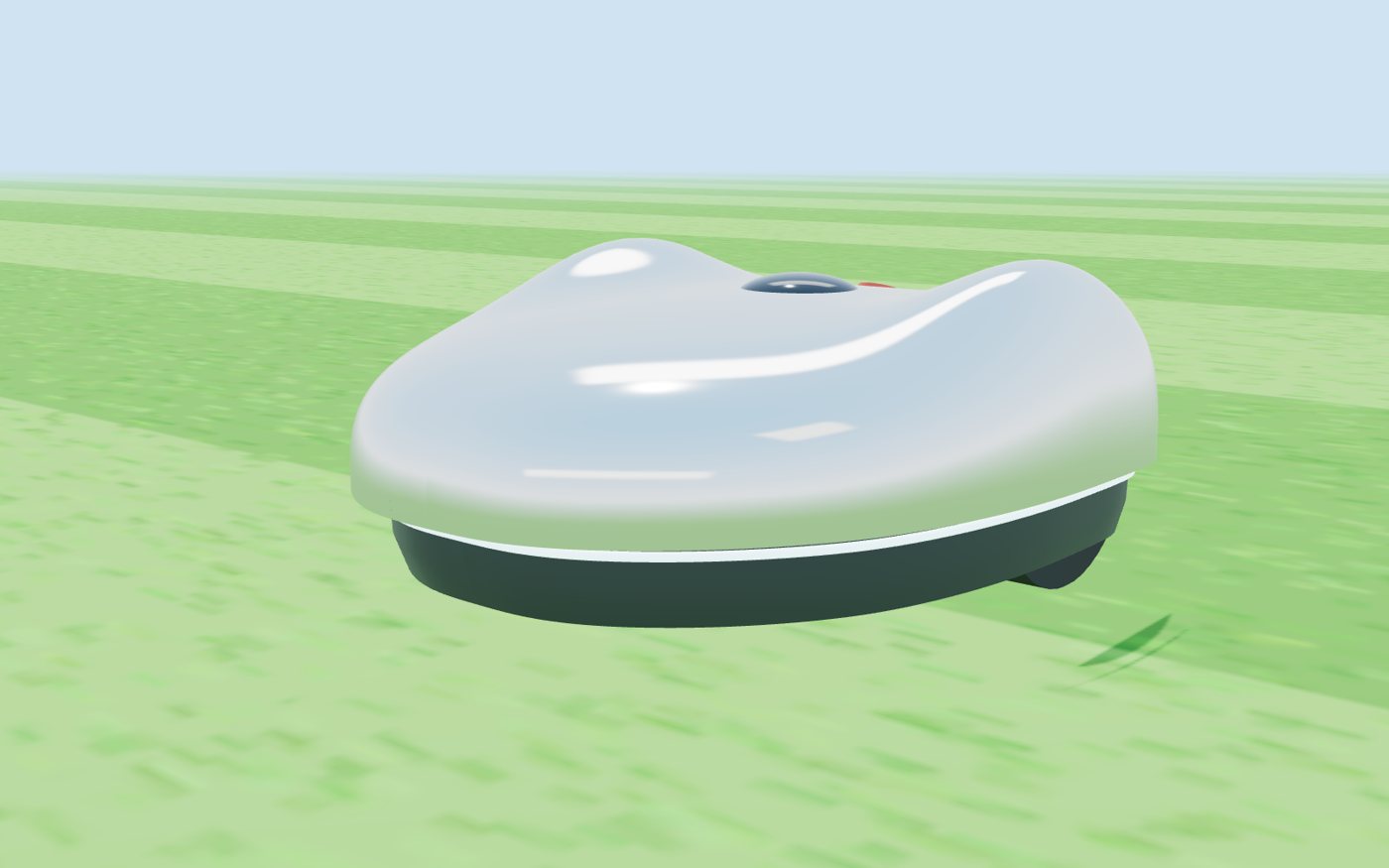
The M1 is a procedural three.js model: about 300 lines of maths in website/js/mower3d.js, rendered to stills in
headless Chromium and live in the browser on the website. Every design move answered a constraint:
- Reverse teardrop. The first render had the wheels sticking out like add-ons. Making the shell widest over the axle, tapering to the nose, gave room to hide them.
- Haunches. The tyres are 240 mm tall and the shell is 245 mm. A car designer's answer is haunches: smooth swells over each wheel. They hide the tyres and give it a crouch.
- A crease you could only see in chrome. The outline's front and rear curves met with a curvature break. On a matte surface you'd never notice; a mirror shows it as a line. We blended the curves with a smoothstep.
- The GNSS eye. A metallised chrome shell would block satellite signals. The RTK antenna sits under a dark glass window at the crown. (Non-conductive vacuum metallisation, used on phone housings, is the thing to test.)
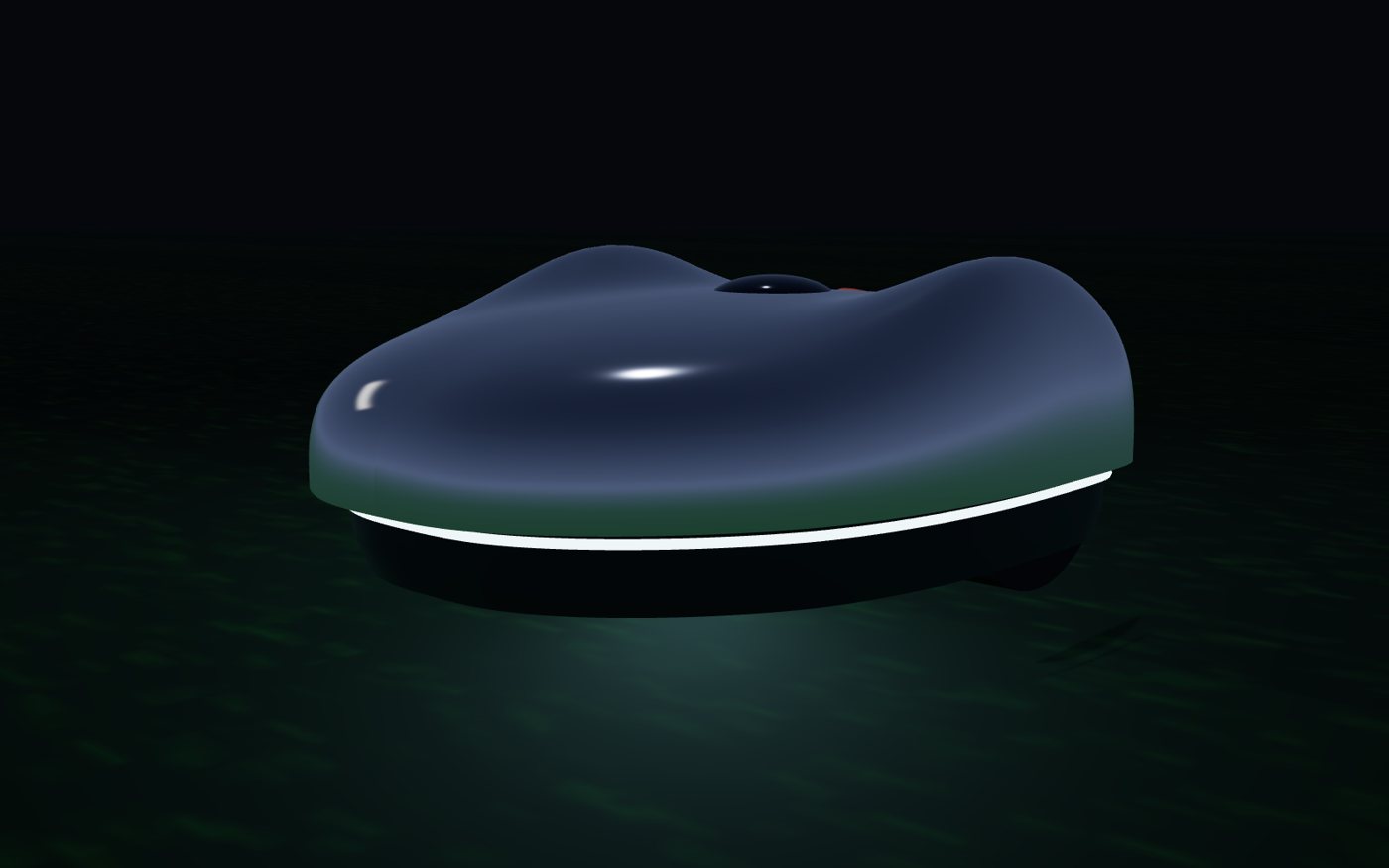
- The light seam. Partly status (cyan positioned, amber blade on, red fault), partly safety: a mirror reflects the lawn, and a robot you can't see is a robot you step on.
Drawings generated from code
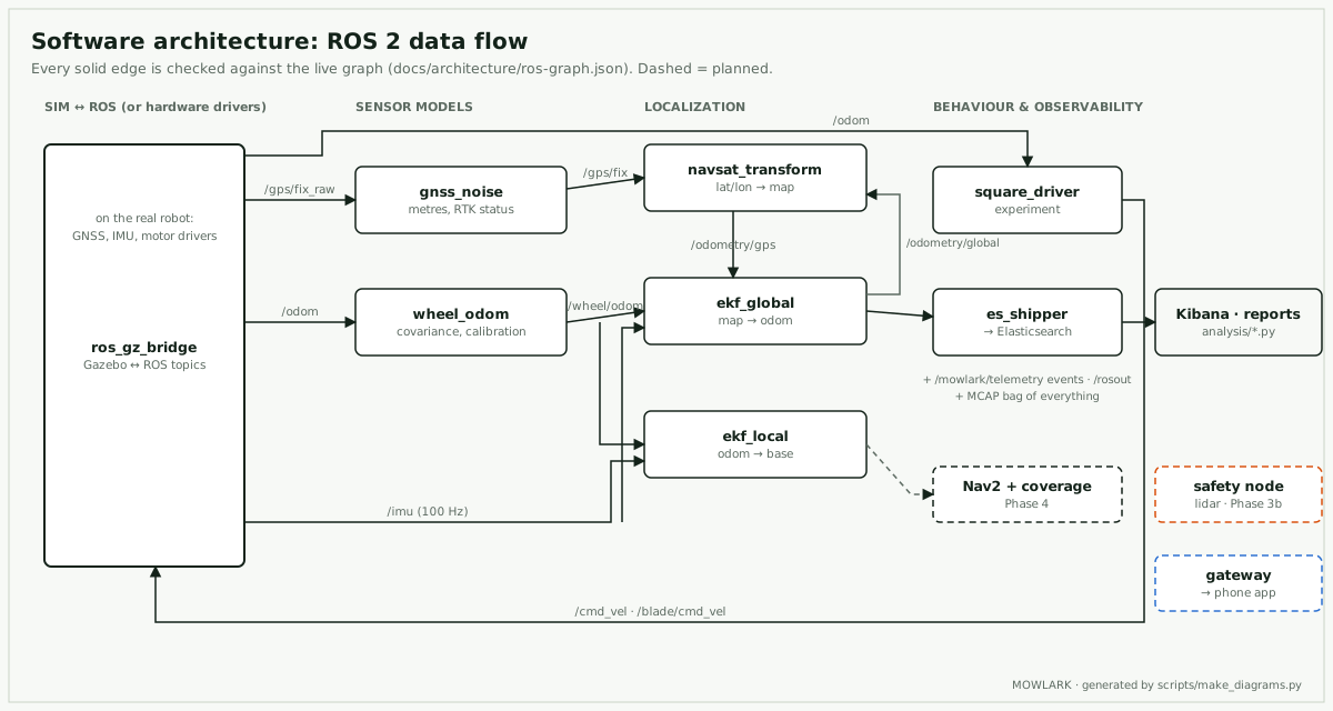
scripts/make_diagrams.py writes six SVG sheets: the power architecture, the blade interlock, the electronics block
diagram, the software data flow, a circuit-board plan and a three-view general arrangement.
Two of them can't drift from reality:
- The software diagram checks itself.
make ros-graphstarts the sim and captures the live ROS graph: 13 nodes, 24 topics, who publishes and who subscribes. Every arrow the diagram draws is asserted against that capture. Rename a topic and the drawing fails to build instead of lying. - The three-view is computed from the 3D model's maths, with silhouettes swept from the same shell function. It immediately caught a mismatch: the sim's GNSS antenna is 420 mm up, but the design puts it under the eye at about 240 mm. That changes the lever arm, so the sensor report needs a rerun when the sim model is updated.
The circuit that matters most
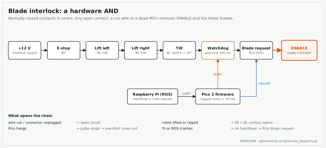
The Mowbot Carrier board plan puts everything safety-critical on one board: power entry, regulators, a Pico 2 safety microcontroller, the IMU, CAN for the motor controllers, and the interlock. The Raspberry Pi becomes replaceable compute. No firmware sits in the blade's critical path: a frozen program can't keep toggling a watchdog pulse.
The plan grew
Chris added lidar ("I don't know how you safely do this without lidar"), object detection and recognition, and a companion iPhone app for the live view, lawn selection and editing, and command and control. They're all in PLAN.md. The short version: lidar becomes the primary obstacle sensor (Phase 3b), the camera says what the lidar found, and the app uses Bluetooth for pairing and basic control and local Wi-Fi for the live map. Bluetooth can't carry lidar.
Next: Phase 3b, lidar in the sim and an obstacle course.